|
HeatersPlus.com Questions? 1-800-442-2581 |
Our secure online ordering website: www.MorElectricHeating.com.
|
| Home | Ordering | Contact Us | Heaters | Controls | Accessories | Search | ||
|
HeatersPlus.com Questions? 1-800-442-2581 |
Our secure online ordering website: www.MorElectricHeating.com.
|
| Home | Ordering | Contact Us | Heaters | Controls | Accessories | Search | ||
HBControls Solid State Relay Assemblies

We are an authorized distributor for
HBControls
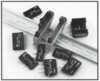
HBControls has developed a family of solid state relay and heat sink assemblies which virtually eliminate the need for any thermal engineering on the part of the design engineer. The assemblies include a convenient DIN rail mounting configuration, finger-safe covers and utilize the highest quality relays available. All of the relays used in the assemblies have received UL, CSA, VDE and CE certification.
Replacement/Crossover of Mercury Relay Contactors
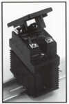 |
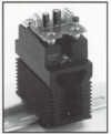
to 40 Amps AC @ 40°C Ambient Replacements for Mercury Relay Contactors |
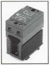 |
SSR DIN Rail Mount to 40 Amps AC @ 40°C Ambient Replacements for Mercury Relay Contactors |
 |
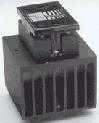
S Series - SSR DIN Rail Mount Power Controller to 25 Amps. HBControls Solid State Relay Assemblies for 0.04 to 25 Amps AC |
 |
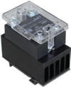
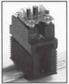
to 40 Amps AC @ 40°C Ambient |
 |
to 10 Amps @ 30°C Ambient |
 |
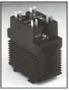
to 60 Amps @ 40°C Ambient |
 |
SCR Power Controller (On/Off) Single Phase to 40 Amps AC @ 40°C Ambient |
 |
to 50 Amps @ 40°C Ambient |
 |
SCR Power Controller Phase Angle 10-40 Amps AC @ 40°C Ambient |
 |
AC Current to DC Voltage |
 |
to 40 Amps AC @ 40°C Ambient |
Complete listing of all HBControls SKU's available for online ordering at www.MorElectricHeating.com
|
We are a Distributor of Industrial, Commercial and Residential Heaters and Controls. Always consult manufacturers installation instructions for proper installation of the products or systems shown on this website. © Copyright 1999-2019 Mor Electric Heating Assoc., Inc. MOR
ELECTRIC HEATING ASSOC., INC. |
| |